 English
 Español
 Deutsch
 Français
 日本語
日本語

By the Pioneer Thermal engineering team
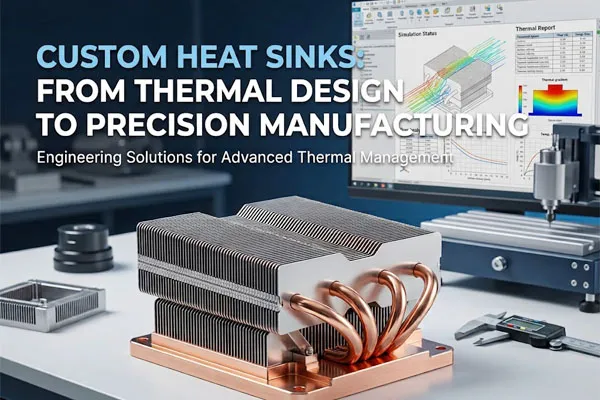
Why choose a custom heat sink?
Catalog heat sinks are a fine starting point. But real products rarely match catalog dimensions. The enclosure is tighter, the airflow is weaker, or three chips with different heights share one cooler.
When that happens, a standard part forces a trade-off: oversize the fan, lose board space, or accept higher junction temperatures. A custom heat sink removes the trade-off by fitting the cooler to your product instead of the other way around.
In our experience, custom designs make the most sense when you have:
• High power density or a hot spot that needs a spreader or heat pipe
• A fixed envelope, such as a sealed housing, LED fixture or telecom unit
• Low or one-directional airflow, or natural convection only
• Weight, cost or noise targets that a standard part misses
Thermal design: start with the numbers
Every project starts with one equation: the temperature rise you can afford divided by the heat you must remove gives you the thermal resistance budget.
Rule of thumb: Rθ = (Tmax − Tambient) ÷ Power. Subtract the resistance of the die, the interface material and any spreader first. What is left is what the heat sink must deliver.
Define the boundary conditions
Before drawing a single fin, we pin down the power, the maximum component temperature, the worst-case ambient temperature, the airflow (or lack of it), and the space available. A missing boundary condition is the most common reason a heat sink passes on paper and fails in the field.
Optimize the fin geometry
Fin height, thickness and spacing pull against each other. Dense fins add surface area but choke airflow. Under natural convection, wider spacing usually wins. Under strong forced air, tighter fins pay off. We use CFD simulation to compare candidates and then confirm the winner on a test bench.
Don't forget the interface
A great fin stack sitting on a poorly flat base with the wrong thermal paste will underperform. We design base thickness, flatness and mounting pressure together with the thermal interface material.
Choosing materials Aluminum covers the majority of applications. Copper is the answer when heat flux is extreme. Many high-performance designs combine both.
| Material | Thermal conductivity (approx.) | Best for | Trade-off |
| Aluminum 6063 | ~200 W/m·K | Extruded profiles, general electronics, LED | Lower conductivity than copper |
| Aluminum 6061 | ~167 W/m·K | CNC-machined parts needing strength | Slightly lower conductivity than 6063 |
| Copper C1100 | ~390 W/m·K | High heat flux, compact designs | About 3x the weight of aluminum, higher cost |
| Copper base + aluminum fins | Hybrid | Hot spot at the base, light fin stack | Extra bonding step |
Choosing the manufacturing process
The best thermal design is worthless if it cannot be made at your target cost and volume. We choose the process together with the geometry, not after it.
| Process | Strengths | Watch out for |
| Extrusion | Low tooling and unit cost, good for medium to high volume | Limited fin height-to-gap ratio; secondary machining often needed |
| CNC machining | Tight tolerances, complex features, fast prototypes | Higher unit cost at scale |
| Skiving | Very thin, dense fins from a single block of metal | Fin height and material limits |
| Bonded / brazed fin | Tall fin stacks, mixed materials | Joint quality must be controlled |
| Heat pipe / vapor chamber | Moves heat away from hot spots to remote fins | Orientation and added cost |
| Die casting | Complex shapes in high volume | Lower conductivity alloys, tooling investment |
Where precision manufacturing matters
Thermal performance is decided by small details that are easy to overlook.
• Base flatness and surface finish. Air gaps at the interface add resistance. A flat, clean contact surface lets the thermal interface material do its job with a thin, consistent layer.
• Hole and pocket position. Mounting holes and component pockets must line up with your PCB or module. Tight positional tolerances avoid uneven clamping pressure.
• Burr-free, consistent fins. Burrs and bent fins change airflow and can damage components during assembly.
• Surface treatment. Anodizing improves corrosion resistance and emissivity, which helps in natural convection. Nickel plating protects copper.
We control these through in-process inspection, first-article checks and documented tolerances on every drawing.
Testing and validation
Simulation narrows the options. Testing settles the question. Typical validation steps include thermocouple measurements on a representative load, comparison against the CFD prediction, and a check of the assembled unit at worst-case ambient temperature. If the results diverge, we update the model, and the next design is better for it.
What to send us for a quote
You do not need a finished drawing. These details let an engineer start on day one:
• Power dissipation of each component (watts)
• Maximum allowed component temperature and ambient temperature
• Airflow: fan model, direction, speed, or natural convection
• Available envelope and any 3D model or sketch
• Mounting method and interface material
• Annual volume and target price, if known
Frequently asked questions
▶When do I need a custom heat sink instead of a standard one?
▶Which is better for heat sinks, aluminum or copper?
▶Can you support prototypes as well as mass production?
▶How do I lower the cost of a custom heat sink?
Talk to a thermal engineer
Send us your requirements and we will recommend a design, material and process, with a clear view of the trade-offs.
 +86-152 2030 1231
 E-mail
